


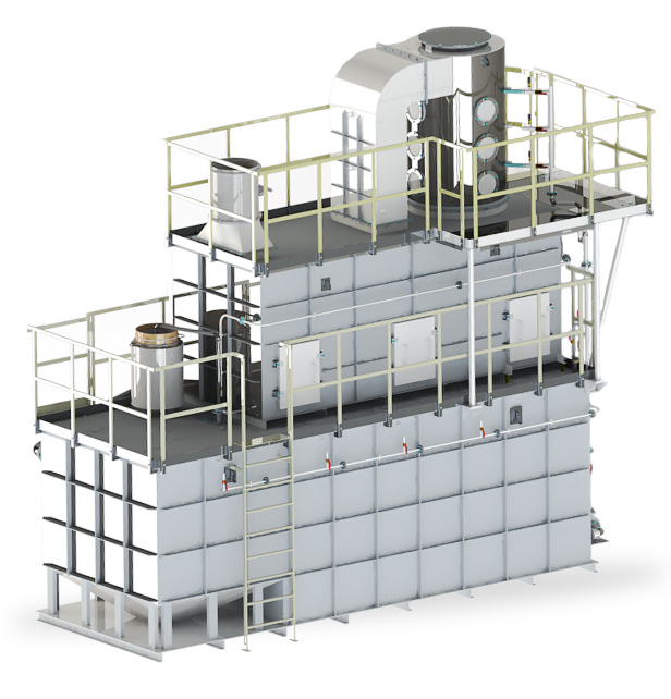
ABU-10
Technical Characteristics and Initial Parameters
for an Absorption-Biological Unit (ABU) with 10000 m3/h (ABU – 10) capacity for ventilated air purification at industrial enterprises
1. ABU-10 technical characteristics and overall dimensions
-
Capturing efficiency for phenol and formaldehyde:
- At least 95%% given input concentration of >20 mg/m3
- At least 85%% given input concentration of 10-20 mg/m3
- At least 80%% given input concentration of 6-10 mg/m3
- At least 70%% given input concentration of 4-6 mg/m3
- Capturing efficiency for suspended substances - at least 98%
-
Purification efficiency against triethylamine and suspended substances between 96% - 99.9% (output triethylamine concertation is no greater than mg/m3)
- Ventilating network resistance: no greater than 1700 Pa
- Hydraulic resistance (ABU’s pressure loss): no greater than 2400 Pa
- Temperature requirements for ABU operations: between +5°C and +30°C
- ABU dimensions in mm if installed as a single unit (Length, Width, Height): 5800x5800x5700
2. ABU-10 Consumables and Electricity Requirements
- Electricity consumption is 36 kW, including a ventilator 30 kW
- Depending on the temperature and humidity of the purified air, ABU requires no greater than 3.0 m3/day of service water to compensate for the water loss during operations.
- No greater than 60.0 Nm3/hour of compressed air is required with 0.2 – 0.7 MPa pressure. Upon request, your ABU unit can come with an installed autonomous blower.
- Between 30-40 kg per year of biogenic additives are required for ABU operations. A variety of agricultural fertilizers containing ammonium, phosphate and potassium ions are used as biogenic additives.
3. ABU-10 Maintenance
ABU maintenance is limited to cleaning its sludge basket from condensed and suspended substances, as well as maintaining a required concertation of phosphorus, nitrogen and potassium in the absorbent by adding biogenic additives (BAs). It is recommended to conduct monthly measurements of phosphorus ions, nitrogen, and potassium to determine if BAs should be added to the absorbent. An indirect indicator (chemical oxygen consumption: COC) is used to gauge absorbent regeneration efficiency by the microorganism. It is also recommended to measure COC on a monthly basis.
4. ABU-10 Initial Installation Requirements.
4.1. Assembly and Premise Requirements
- Provide concrete flooring at the 0.000 mark for ABU placement. The floor should be leveled using the Level instrument. Thickness of the concrete floor will depend on the projected ABU load. ABU is installed on two frames.
- The load per frame is no greater than 25 tones.
- No floor attachments are required.
-
Provide drainage traps in the concrete floor in case of an emergency spillage. The traps should be connected to the workshop’s sewerage system. An emergency spillage is defined as a leakage in the body of the tank or a leakage in the flow shut-off and control valves and related systems.
No greater than 8 m3 of spillage will be produced per one emergency.
Composition of an emergency spillage is as follows:
- No greater than 150 mg/litre of phosphates
- No greater than 200 mg/litre of nitrates
- pH value between 6.5 - 8.3
- Chemical Oxygen Consumption (COC) no greater than 6,000 mg O2/litre
- Contains no greater than 0.1% by volume of suspended substances with particles’ size of less than 0.2 mm.
- No hoisting mechanisms are required for ABU maintenance.
- Ambient room temperature for an ABU should not be less than +5°C during the coldest month of the year, and also should not exceed the +30°C mark.
- ABU installation room should adhere to lowest fireproof and explosion proof category requirements (the room contains cold and/or incombustible substances and materials in such amounts that the fire load does not exceed 100 mJ/m2 in their respective locations, and the fire load of the entire room is under 1000 mJ.)
4.2 Electricity Requirements
-
Electric Supply:
- Ventilator engine (1 pc., 380 V, 30 kW)
- Water pump engines (1 pc., 380 V, 2.2 kW)
- Sludge pump engines (1 pc., 380 V, 2.2 kW)
- ABU electric valve drivers – 9 pcs., 220 V, 100 W. (combined consumption for all 9 pcs.)
- Level sensors – 3 pcs, 6 W (combined consumption for all 3 pcs.)
Power cables, cable trays, and control cables are supplied with ABU.
- Control cabinets are also supplied with ABU.
- Provide power circuit wiring from workshop’s transformer to ABU’s control cabinets.
- Both the power and start-up equipment for the pump and the ventilator should be installed in accordance to the «Electrical Equipment Installation Rules» and in locations that allow for monitoring of such equipment.
- Provide grounding busbars for all ABU non-conducting parts.
4.3. Water supply
- Provide for industrial water supply to ABU Ду 20 fitting for a one-time filling of the tanks (about 20 m3) when the ABU is started.
- Compensatory water consumption by the ABU - 2.0 m3/day max.
-
Requirements for industrial water to be used as additional feeding:
- pressure - 0.2-0.6 MPa;
- mechanical impurities content - 0.1% max by volume, particle size - 0.2 mm max;
- Temperature between +5°С and +30°С
- With the ABU absorption system running (pump and ventilator are ON), service water intended for compensatory supply can be absent for 2 hours max. If the absorption system is not running (pump and ventilator are OFF), additional supply of water is not required.
4.4. Compressed air
- Compressed air consumption per one ABU unit does not exceed 80 N3/h.
- Provide a 15 mm in diameter pipeline to supply ABU with compressed air.
- Compressed air requirements:
- Pressure between 2 - 7 atm.
- Should contain no greater than 10 mg/m3 of suspended substances.
- Moisture content – no requirements.
- Compressed air should be supplied 24/7. Maximum allowed time without compressed air supply is no greater than 2 hours. A situation when an ABU unit is deprived of compressed air for longer than 2 hours is defined as abnormal. The necessary procedures for resolving abnormal situations are outlined in the ABU’s passport/documentation.
4.5. Ventilation
- Provide air ducts to supply ventilated air from your manufacturing line to ABU, and then from ABU to the atmosphere.
-
As a thrust actuator, ABU is using VIR400-5-1-LG0-180M2-O-P-U1 ventilator with the following characteristics:
- engine 30 kW, 380/660V, 50Hz, 2950 rpm
- the ventilator is made of carbon steel with a powder coating
- ventilator impeller rotation speed is 2950 rpm
- VIR400-5-1-LG0-180M2-O-P-U1 ventilator’s noise level is 113 dB.
An alternative thrust actuator produced by another manufacturer with different characterises can also be used.
- Pressure at the ABU’s ventilating air intake and exhaust points is no greater than –1200 Pa and +500 Pa, respectively.
- ABU room should have an installed ventilation system capable of providing 3-4 air changes per day.
5. Life cycle
Service cycle is at least 15 years.